If you have a photovoltaic system on your house’s roof, you probably know the problem. During some times of the day, e.g. at noon, you have a lot of sun on the roof and therefore also a lot of self-produced excess energy which will be exported to the grid but will not be paid well. During other times of the day, e.g. at night, you have no or rarely sun on the roof and therefore no or rarely self-produced energy, hence you either have to use up the energy stored in your battery (if you have one) or you have to import energy from the grid at high cost.
So when you think about when certain electricity consumers with high energy needs like a washing machine or a tumble dryer should run, it would definitely make sense to let them run during times of the day when you have a lot of self-produced excess solar energy. This is especially important during winter times when at night the energy stored in the battery is needed for the lights and heating and therefore we should ensure to reserve energy for those use cases and not use up the precious energy stored in the battery for high energy consuming devices like a washer or a dryer.
The following image shows the energy flow in my house for a typical fall day. During winter you would most likely even see energy import from grid at night as soon as the battery is used up.

But how can we ensure that we use the washer and the dryer only during the optimal time when a lot of excess solar energy is available on the roof and how can we make all house residents aware of this?
The next chapters will explain in detail how to build a smart advisor device that solves this challenge. What you need:
- An ESP dev board (can actually be nearly any kind of ESP board, you especially have to ensure that the housing you design will have the right dimensions of the screw holes to hold it)
- A GC9A01 round TFT display
- Some jumper wires, a USB cable for powering the ESP dev board and some M2 screws for attaching the ESP dev board to the housing
- A Home Assistant installation with ESPHome AddOn and an integration of your inverter
- A CAD app (e.g. Fusion 360), a slicer app (e.g. Cura) and a 3D printer with filament in the color you want the advisor device to be
I have created an overview video for the following instructions which can be found here. The video can be used as an intro to get a basic understanding:
Step 1: Flash ESP32 dev board with ESPHome and integrate with Home Assistant.
The first step is to flash the ESP32 dev board with ESPHome and integrate it with Home Assistant. This is fairly easy — just open https://esphome.io/projects/ and follow the steps to create a “Empty ESPHome device”.
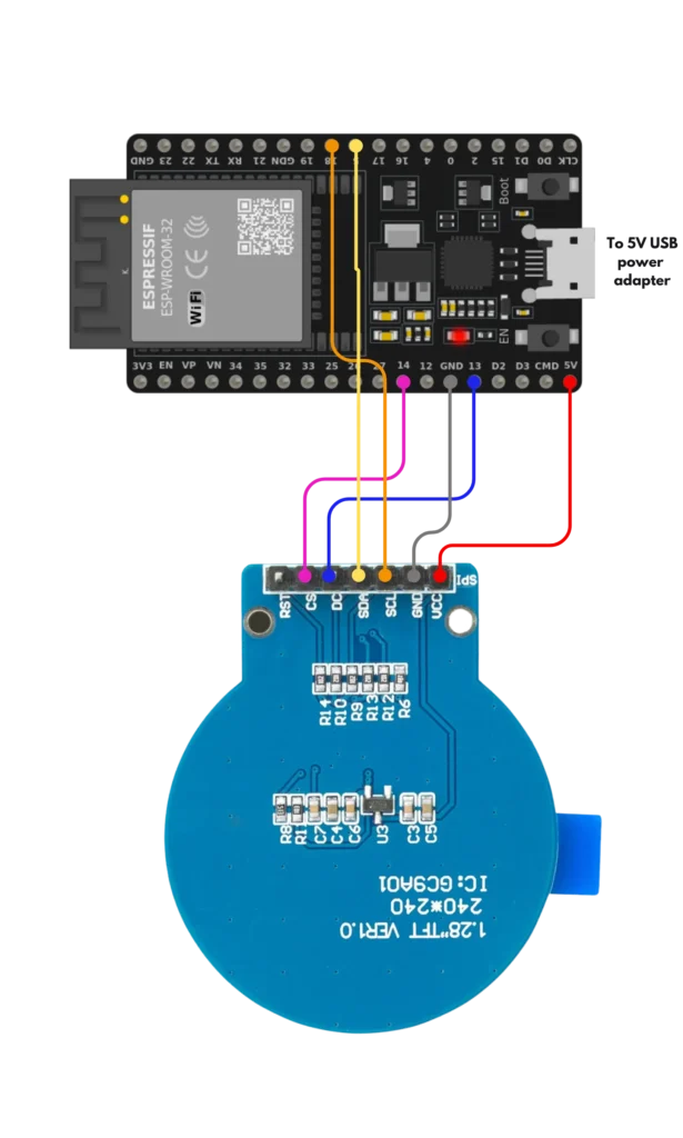
Step 2: Set up wiring from GC9A01 TFT display to ESP dev board.
Prepre wiring as shown in below picture
Step 3: Set up Home Assistant integration “Forecast.Solar” for forecasting your daily solar energy yield.
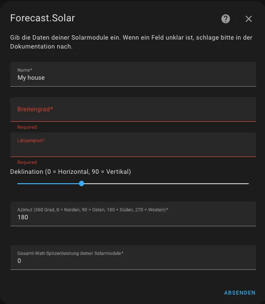
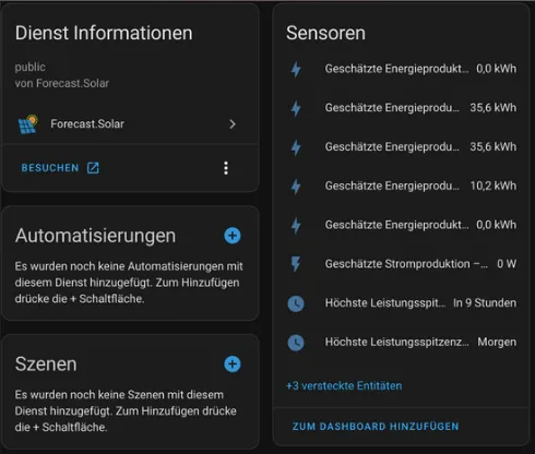
Install the Home Assistant Add-On „Forecast.Solar“. When installing, you have to make some config, for example you have to define the GPS location of your solar modules, the peak power as well as the direction in which the modules face.
Step 4: Develop ESPHome YAML file and flash to ESPHome device.
Now you have to create the ESPHome YAML file which will include the sensors you want to sync with Home Assistant as well as the logic for displaying the traffic light status colors.
An example YAML file can be found here:
esphome:
  name: "smart-washer-dryer-advisor"

esp32:
  board: esp32dev
  framework:
    type: arduino

# Logging aktivieren
logger:

# Home Assistant API aktivieren
api:
  encryption:
    key: <DEIN_VERSCHLÜSSELUNGSSCHLÜSSEL>

ota:

wifi:
  ssid: !secret wifi_ssid
  password: !secret wifi_password

  # Fallback-Hotspot (Captive Portal) aktivieren, falls die WLAN-Verbindung fehlschlägt
  ap:
    ssid: <DEIN_FALLBACK_HOTSPOT_SSID>
    password: <DEIN_FALLBACK_HOTSPOT_PASSWORT>

captive_portal:

# Importiere das Modul zum Steuern des GC9A01 TFT-Displays
external_components:
   - source: github://the-smart-home-maker/esphome-4cello@gc9a01
     components: [ gc9a01 ]

spi:
  mosi_pin: GPIO5
  clk_pin: GPIO18

# Definiere das Display-Komponent
# Die Lambda-Funktion enthält die Logik zur Anzeige der Daten auf dem Display
display:
  - platform: gc9a01
    id: my_round_screen
    cs_pin: GPIO14
    dc_pin: GPIO13
    rotation: 270
    lambda: |-
      auto red = Color(255, 0, 0);
      auto green = Color(0, 255, 0);
      auto yellow = Color(255, 255, 0);
      auto white = Color(255, 255, 255);
      auto black = Color(0, 0, 0);
      auto left_center = 30;
      auto top_center = 120;
      it.strftime(85, 20, id(roboto_medium), "%H:%M", id(hass_time).now());
      if(id(house_battery_charging_state).state > 30 && id(car_charging_power).state == 0 && (id(energy_current_hour).state > 1 || id(solar_production).state > 1000)) {
        it.filled_circle(left_center + 45, top_center, 20, green);
        it.image(left_center + 35, top_center - 12, id(lightning), green, black);
        it.printf(left_center + 35 + 45, top_center+12, id(roboto_medium), TextAlign::BASELINE_LEFT, "Now!");
      } else if (id(energy_next_hour).state > 1) {
        it.filled_circle(left_center, top_center, 20, yellow);
        it.image(left_center - 10, top_center - 12, id(lightning), yellow, black);
        it.printf(left_center + 35, top_center+12, id(roboto_medium), TextAlign::BASELINE_LEFT, "Check soon");
      } else {
        if(id(energy_production_today_remaining).state < 5) {
          it.filled_circle(left_center + 10, top_center, 20, red);
          it.image(left_center, top_center - 12, id(lightning), red, white);
          it.printf(left_center + 45, top_center+12, id(roboto_medium), TextAlign::BASELINE_LEFT, "Tomorrow");
        } else {
          it.filled_circle(left_center, top_center, 20, red);
          it.image(left_center - 10, top_center - 12, id(lightning), red, white);
          it.printf(left_center + 35, top_center+12, id(roboto_medium), TextAlign::BASELINE_LEFT, "Later today");
        }
      }
      switch (id(page)){
        case 1:
          it.image(110, 160, id(sun), black, white);
          it.printf(120, 200, id(roboto_small), TextAlign::CENTER, "Now: %.0f W", id(solar_production).state);
          break;
        case 2:
          it.image(110, 160, id(sun), black, white);
          it.printf(120, 200, id(roboto_small), TextAlign::CENTER, "Next 1h: %.0f kWh", id(energy_next_hour).state);
          break;
        case 3:
          it.image(110, 160, id(sun), black, white);
          it.printf(120, 200, id(roboto_small), TextAlign::CENTER, "Rest today: %.0f kWh", id(energy_production_today_remaining).state);
          break;
        case 4:
          it.image(110, 160, id(sun), black, white);
          it.printf(120, 200, id(roboto_small), TextAlign::CENTER, "To grid: %.0f W", id(power_to_grid).state);
          break;
        case 5:
          it.image(110, 160, id(battery), black, white);
          it.printf(120, 200, id(roboto_small), TextAlign::CENTER, "Battery: %.0f %%", id(house_battery_charging_state).state);
          break;
      }

# Schriften definieren
font:
  - file: "gfonts://Roboto"
    id: roboto_small
    size: 18
    glyphs: "!%()+=,-_.:°0123456789ABCDEFGHIJKLMNOPQRSTUVWXYZabcdefghijklmnopqrstuvwxyzä "
  - file: "gfonts://Roboto"
    id: roboto_medium
    size: 30
    glyphs: "!%()+=,-_.:°0123456789ABCDEFGHIJKLMNOPQRSTUVWXYZabcdefghijklmnopqrstuvwxyzä "
  - file: "gfonts://Roboto"
    id: roboto_large
    size: 40
    glyphs: "!%()+=,-_.:°0123456789ABCDEFGHIJKLMNOPQRSTUVWXYZabcdefghijklmnopqrstuvwxyzä "

# Icons definieren
image:
  - file: "sun.png"
    id: sun
  - file: "battery-outline.png"
    id: battery
  - file: "lightning-bolt.png"
    id: lightning

# Zeit von Home Assistant abrufen
time:
  - platform: homeassistant
    id: hass_time

# Alle Sensoren definieren, die mit Daten aus deinen Home Assistant-Sensoren gefüllt werden sollen
sensor:
  - platform: homeassistant
    name: "Energy next hour" # vorhergesagte Energie für die nächste Stunde, die vom Home Assistant-Add-On “Forecast.Solar” kommt
    id: energy_next_hour
    entity_id: sensor.<SENSOR_FORECAST_SOLAR_NEXT_HOUR>
    force_update: true
  - platform: homeassistant
    name: "Energy current hour" # vorhergesagte Energie für die aktuelle Stunde, die vom Home Assistant-Add-On “Forecast.Solar” kommt
    id: energy_current_hour
    entity_id: sensor.<SENSOR_FORECAST_SOLAR_CURRENT_HOUR>
    force_update: true
  - platform: homeassistant
    name: "Energy production today remaining" # vorhergesagte verbleibende produzierte Energie für den Rest des Tages, die vom Home Assistant-Add-On “Forecast.Solar” kommt
    id: energy_production_today_remaining
    entity_id: sensor.<SENSOR_FORECAST_ENERGY_TODAY_REMAINING>
    force_update: true
  - platform: homeassistant
    name: "Solar production" # aktuelle Solarproduktion, die von deinem Wechselrichter kommt
    id: solar_production
    entity_id: sensor.<SENSOR_INVERTER_CURRENT_PRODUCTION>
    force_update: true
  - platform: homeassistant
    name: "Power to grid" # Energie, die derzeit ins Netz eingespeist wird
    id: power_to_grid
    entity_id: sensor.<SENSOR_INVERTER_POWER_TO_GRID>
    force_update: true
  - platform: homeassistant
    name: "House battery charging state" # aktueller Ladezustand deines Hausakkus
    id: house_battery_charging_state
    entity_id: sensor.<SENSOR_INVERTER_CURRENT_BATTERY_STATE>
    force_update: true
  - platform: homeassistant
    name: "Car charging" # lädt das E-Auto

 derzeit (wenn ein großer Verbraucher wie mein Auto derzeit lädt, sollte ich die Waschmaschine/Trockner nicht einschalten, um nicht noch mehr Energie zu verbrauchen)
    id: car_charging_power
    entity_id: sensor.<SENSOR_CAR_CHARGING>
    force_update: true

globals:
- id: page
  type: int
  initial_value: "1"

interval:
- interval: 15s
  then:
    - lambda: |-
        id(page) = (id(page) + 1);
        if (id(page) > 5) {
          id(page) = 1;
}There are a couple of place holders in the file which you need to fill out.
<YOUR_ENCRYPTION_KEY>, <YOUR_FALLBACK_HOTSPOT_SSID> and <YOUR_FALLBACK_HOTSPOT_PASSWORD> are general ESPHome settings and will therefore not be explained here in detail.
All placeholders that start with <SENSOR… are names of your sensors in Home Assistant which you want to propagate to ESPHome so that you can use those to create your specific traffic light logic. Those included in the YAML file shown above are just examples. You can chose which ever you like.
After creating the file, you have to flash it to the ESPHome device. This can be performed wirelessly.
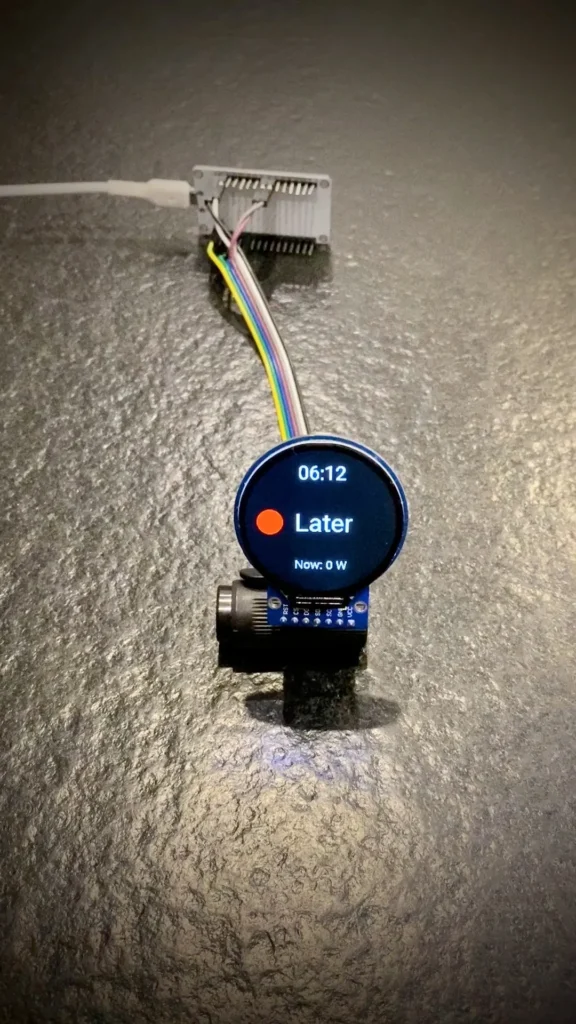
Step 5: Try out whether display works as expected and data is displayed correctly.
After having flashed the ESPHome YAML configuration to the ESP dev device, it is time for a first test.If everything works as expected, it should look something like this:
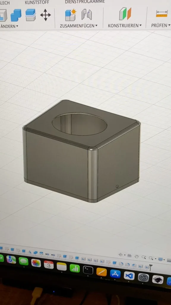
Step 6: Design housing in CAD app and export as STL file.
Next step is to design a housing with a CAD app.
I already prepared a housing which you can download from my printables profile if you like:
https://www.printables.com/de/model/610431-smart-advisor-device-for-when-to-turn-on-the-washi
Step 7: Slice STL file with slicer app and send to 3D printer for printing.
You can now slice the STL file with your favorite slicer app (e.g. Cura) and then send it to your 3D printer for printing:
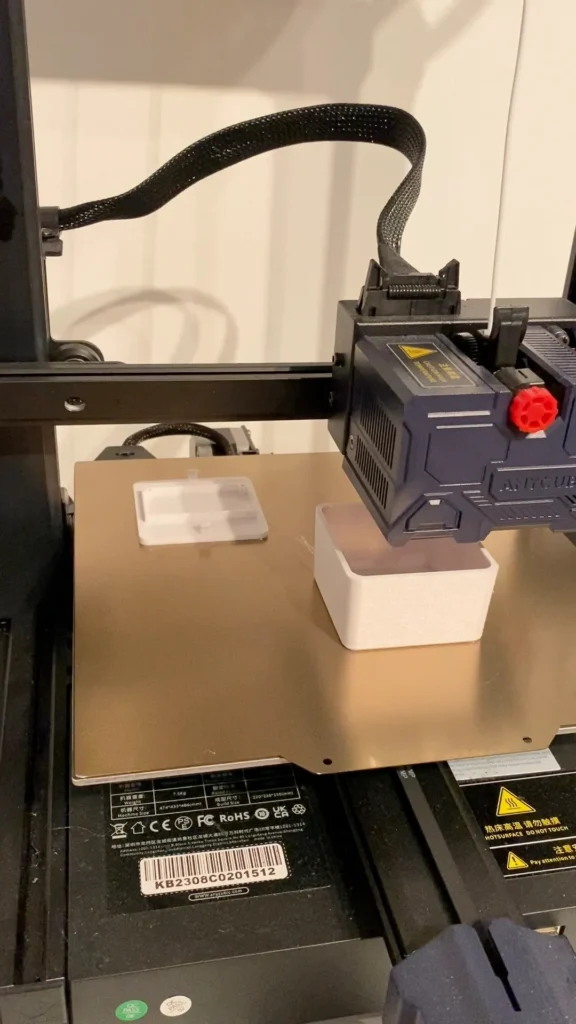
Be aware that the picture here shows white filament. After playing around a little, I figured out that I like a black coloring more and that’s why in further images (step 8 and above) you will find a black housing.
Step 8: Glue the display into the top part of the housing with hot glue.
Glue the display into the top part of the housing with hot glue:
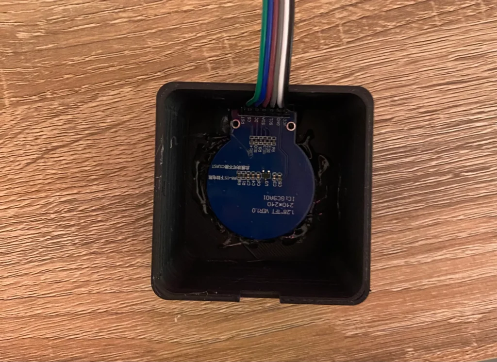
Make sure that it is well aligned and there is no glue getting into the display. From the other side, it should look like this:
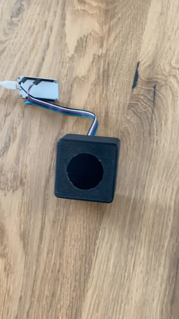
Step 9: Attach ESP dev board to the bottom part of the housing with M2 screws.
Attach the ESP device board to the bottom part of the housing using M2 screws:
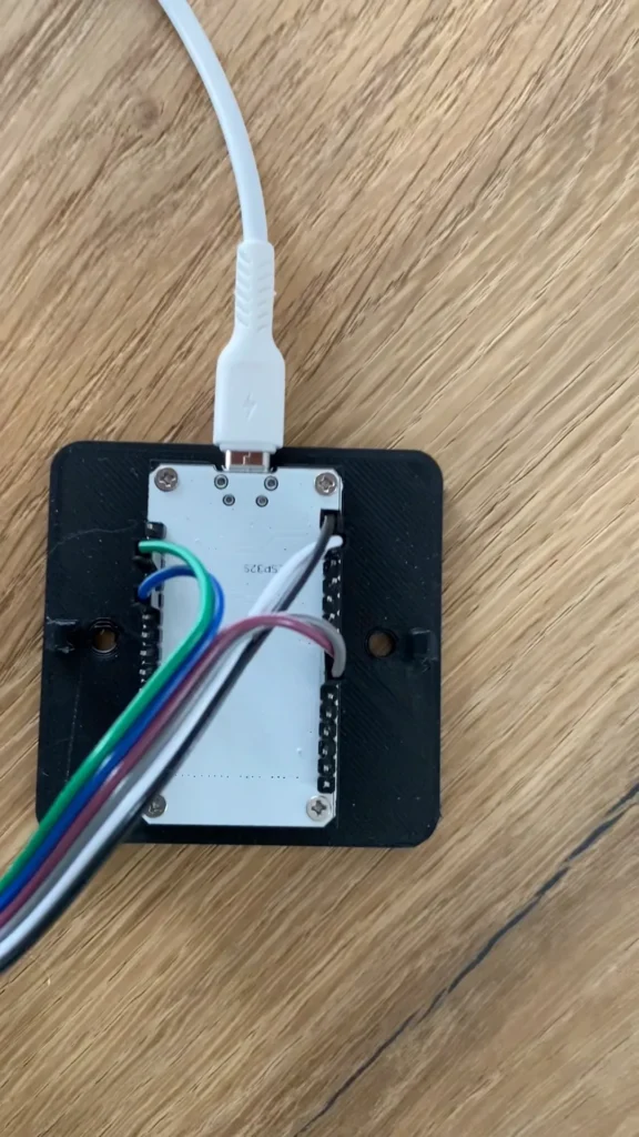
Step 10: Attach bottom part of housing to wall and afterwards attach top part of housing to bottom part.
Now you just have to attach the bottom part of the housing to the wall (either with screws or with double sided tape). Once this is done, you can attach the top part of the housing (including the display) to the bottom part, power it and you’re done 😀👍🏻


2 Responses
I’m currently doing this with an ESPHome lightbulb just showing the colour. Mine is a bit more complicated because I don’t just have solar but also wholesale energy that varies and spikes an price.
I’m thinking of upgrading to a flashed version of the Ulanzi clock which can show the incoming forecast pricing and also take into account the solar output. An HA blueprint would be useful here too as it gets quite complicated. Especially if you want to turn appliances off during a spike.
Let me know if you are thinking of updating your project at any point.
Hi Michael,
the solution with a colored lightbulb also sounds great and simple 😊👍🏻 My intention was to add some information about the forecasted energy for the day, the current energy etc. that’s why I chose the display solution.
And I am also considering switching to dynamic pricing for my remaining energy pulled from the grid and would like to include this to the traffic light display as well. So I will definitely post an update in case I will be going there 😊
Best,
The Smart Home Maker