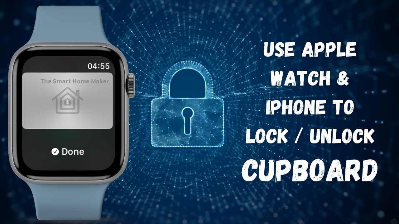
Looking to level up your home automation? 🔒 In this tutorial, I am going to show you how to build a smart lock for your cupboard, drawer, or any other spot you want to secure—all controllable with your Apple Watch or iPhone! 📱🔓
This project integrates seamlessly with Home Assistant using ESPHome and also connects with Apple HomeKit for a smooth, user-friendly experience. Whether you’re a smart home enthusiast or just looking for a fun and practical DIY project, this guide has everything you need to get started.
Let’s dive into the world of smart security and convenience—right at your fingertips!
Here you can find the full tutorial in the form of a YouTube video:
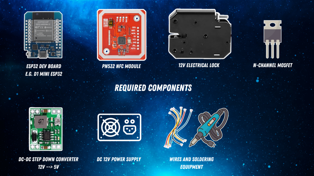
Required components
You need the following components:
- ESP32 dev board, e.g. a D1 mini ESP32
- PN532 NFC tag reader component
- Electrical lock, e.g. 12V electrical locker lock
- N-channel MOSFET to turn on/off the electrical lock
- Maybe a step-down converter to convert the voltage between the lock (in my case 12V) and the ESP32 dev board (3.3V / 5V)
- Power supply (in my case a 12V power supply)
- Some wires and soldering equipment

Wiring scheme
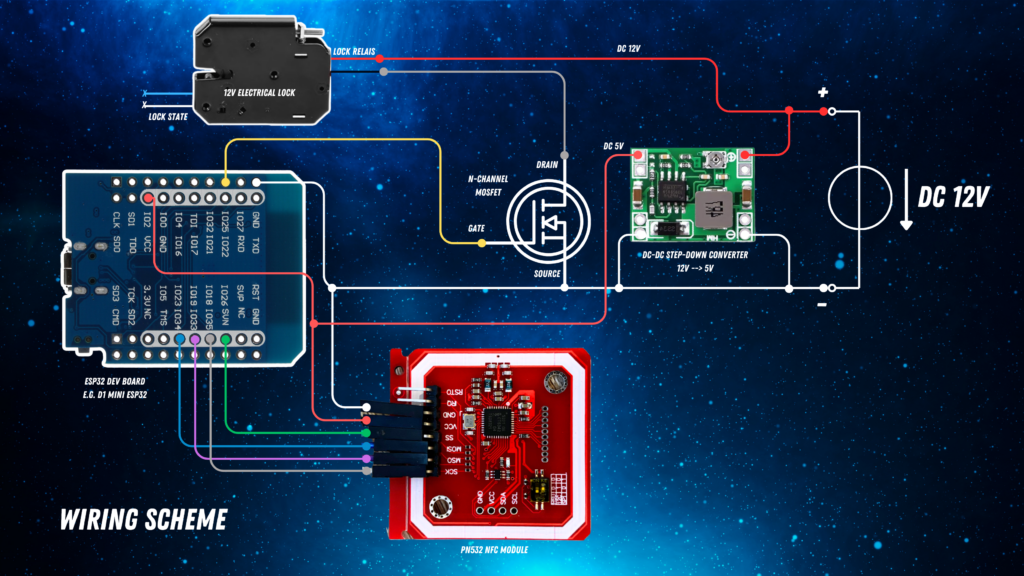
The following diagram shows you the wiring scheme.

You can see the ESP32 dev board – here a D1 mini ESP32 – on the left side. This is the heart of the architecture and controls what happens.
There is a DC 12V power source shown on the very right side of the wiring scheme. We need 12V for the electrical lock. The green component is a DC-DC step-down converter which converts the 12V down to 5V to supply the D1 mini.
On the top you can find the electrical 12V electrical lock. It has two cable pairs. One is for reading the lock state (blue/white) and one is for controlling the lock state (red/black). The 12V electrical lock is controlled by the N channel mosfet which you can see in the center of the image. The gate pin of the MOSFET controls whether current can flow through it, hence whether the lock will be supplied or not. The gate is connected to GPIO25.
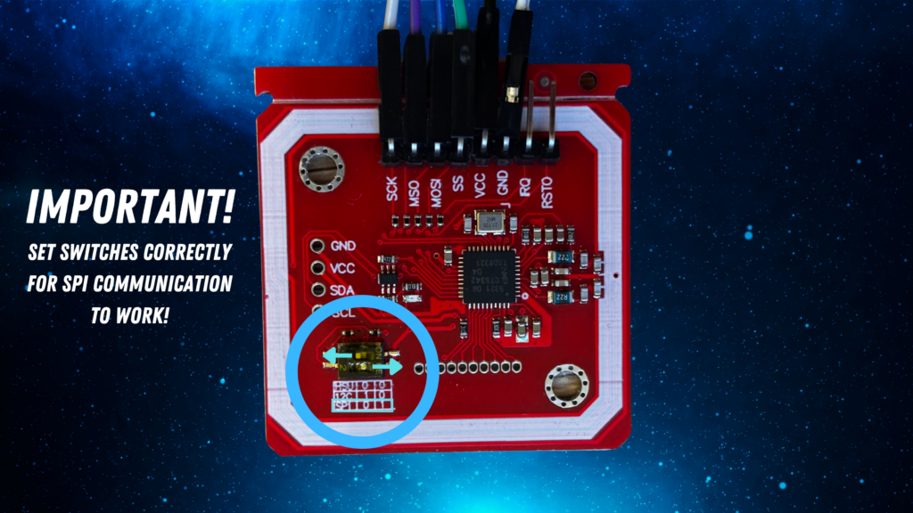
The red component on the bottom right is the PN532 NFC reader which needs to be connected to 5V power and GND. Also it gets connected to the D1 mini via SPI, so just use the GPIOS as shown in the diagram – SCK goes to GPIO18, MSO goes to GPIO19, MOSI goes to GPIO23 and SS goes to GPIO26. For the PN532 NFC reader, it is important to enable SPI communication. For that, please make sure to set the little switches on the board correctly. For the model I got you can see how you have to set the switches to enable SPI communication. The little table below the switch tells you which switch to flip in which direction to enable SPI:

ESPHome YAML code
After we have wired everything up, we need to prepare, compile and flash the software to the D1 mini ESP32. We use ESPHome for that which allows for a super simple configuration just using YAML files. To understand how you can compile and flash ESPHome code to the D1 mini, please follow the official docs. In the following listing, you can find the ESPHome YAML code.
The assumption is that you have wired everything exactly as shown above, so all the GPIOs match. Please be aware that YOUR_ENCRYPTION_KEY, YOUR_OTA_PASSWORD and YOUR_AP_PASSWORD are just placeholders as those are keys/passwords that are usually auto generated by ESPHome. Please note that instead of YOUR_TAG_ID you have to enter the tag ID of your static NFC tag that you want to use. The full explanation of the code can be found in the YouTube video linked above.
esphome:
  name: smart-cupboard-lock
  friendly_name: smart-cupboard-lock

esp32:
  board: esp32dev
  framework:
    type: esp-idf
    version: 5.2.1
    platform_version: 6.7.0
    sdkconfig_options:
      CONFIG_COMPILER_OPTIMIZATION_SIZE: y
      CONFIG_LWIP_MAX_SOCKETS: "16"
      CONFIG_MBEDTLS_HKDF_C: y

# Enable logging
logger:

external_components:
  - source: github://rednblkx/HAP-ESPHome@main

# Enable Home Assistant API
api:
  encryption:
    key: YOUR_ENCRYPTION_KEY

ota:
  - platform: esphome
    password: YOUR_OTA_PASSWORD

wifi:
  ssid: !secret wifi_ssid
  password: !secret wifi_password

  # Enable fallback hotspot (captive portal) in case wifi connection fails
  ap:
    ssid: "Smart-Cupboard-Lock"
    password: YOUR_AP_PASSWORD

captive_portal:

spi:
  clk_pin: GPIO18
  miso_pin: GPIO19
  mosi_pin: GPIO23

pn532_spi:
  id: nfc_spi_module
  cs_pin: GPIO26
  update_interval: 100ms
  on_tag:
    then:
      lambda: |-
        ESP_LOGI("INFO", "My Tag ID is: %s", x.c_str());
        if(x == YOUR_TAG_ID) {
          if (id(cupboard_lock).state == LOCK_STATE_LOCKED) {
            id(cupboard_lock).unlock();
          } else {
            id(cupboard_lock).lock();
          }
        }

homekit_base:
  setup_code: '466-37-726'

homekit:
  lock:
    - id: cupboard_lock
      nfc_id: nfc_spi_module
      on_hk_success:
        lambda: |-
          ESP_LOGI("INFO", "IssuerID: %s", x.c_str());
          ESP_LOGI("INFO", "EndpointID: %s", y.c_str());
          if (id(cupboard_lock).state == LOCK_STATE_LOCKED) {
            id(cupboard_lock).unlock();
          } else {
            id(cupboard_lock).lock();
          }
      on_hk_fail:
        lambda: |-
          ESP_LOGI("ERROR", "Authorizing HomeKit lock failed");
      hk_hw_finish: "SILVER"

button:
- platform: homekit_base
  factory_reset:
    name: "Reset Homekit pairings"

lock:
  - platform: template
    id: cupboard_lock
    name: "HomeKit Cupboard Lock"
    optimistic: True
    on_lock:
    - logger.log: "Door Locked!"
    - switch.turn_off: electronic_lock
    on_unlock:
    - logger.log: "Door Unlocked!"
    - switch.turn_on: electronic_lock
    - delay:  100ms
    - switch.turn_off: electronic_lock

output:
  - platform: gpio
    pin: GPIO25
    id: 'lock_out'
switch:
  - platform: output
    id: electronic_lock
    output: 'lock_out'
Try it out
Once your code has been flashed to the D1 mini, you should be able to add the HomeKit Bridge to Apple Home. Just tap on the “+” icon in your Apple Home app, choose “Add device”, select “Further options” and then you should see the new HomeKit Bridge – be aware that you need to type in the setup_code that you have defined in homekit_base (in my case 466-37-726). You should also be able to add the ESPHome device to Home Assistant to control the lock from there. See the YouTube video linked above for a demo how it should work. Enjoy!


4 Responses
Amazing!
Hi, one question. How I can get the tag ID of my Apple Watch? And I have actually another question, what if I would like to use two or more devices (more person)?
Thank you!
Tomas
Hi Tomas,
as far as understand the Apple Home Key mechanism, there is not a static tag ID for the Apple Watch / iPhone but a dynamic one.
Sharing access with family members can be done by adding them to the Apple Home App.
Best regards
The Smart Home Maker
Nice project
Do have a question about it. If I have to restart the esp32, the lock opens by default, can this be solved in the code? Gr Stefan
Hi Stefan,
happy that you like the project 😊
If the switch controlling the lock is always turned on at reboot (i.e. that GPIO25 is pulled high at startup), it might be useful to add a pulldown resistor on the GPIO25 – maybe 4.7 kilo ohms between the pin and ground. But I can not guarantee that this will solve the issue as I haven’t tried it out.
Best regards
The Smart Home Maker